Difference between revisions of "Vickers Fire Control Instruments"
(use Citable Source Templates in place of longhand <ref>s) |
|||
| (6 intermediate revisions by one other user not shown) | |||
| Line 2: | Line 2: | ||
==Dial Instruments== | ==Dial Instruments== | ||
| + | :<small>([[Vickers Dial Fire Control Instruments|main article]])</small> | ||
| + | <gallery widths=240px> | ||
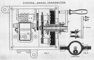
| + | File:HFCI1914Plate7.jpg | '''Range Transmitter'''{{HFCI1914|Plate 7}} | ||
| + | File:HFCI1914Plate8.jpg | '''Range and Deflection Receiver'''{{HFCI1914|Plate 8}} | ||
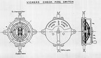
| + | File:HFCI1914Plate9.jpg | '''Check fire switch'''<ref>''Handbook forf Fire Control Instruments, 1914'', Plate 9.</ref> | ||
| + | </gallery> | ||
| − | + | Vickers "dial instruments" were step-by-step devices more accurately referred to as "cyclometric instruments", like those of [[Barr and Stroud Fire Control Instruments|Barr and Stroud]]. That is, they did not indicate on a clockface, but digitally, as an old-time speedometer. | |
| − | |||
| − | |||
| − | |||
| − | |||
| − | |||
| − | + | The range and deflection transmitters had tell-tale receivers built into them to indicate the value, and a single handle by which to drive the value through its range. | |
There were no separate order instruments, but the transmitters featured a 3 position "check fire switch" could be set to "Control Fire" or "Check Fire" to cause the receivers to expose a red or a white disc, respectively. The intermediate position of this switch was labelled "Off" and removed power from the attached instruments entirely. | There were no separate order instruments, but the transmitters featured a 3 position "check fire switch" could be set to "Control Fire" or "Check Fire" to cause the receivers to expose a red or a white disc, respectively. The intermediate position of this switch was labelled "Off" and removed power from the attached instruments entirely. | ||
==F.T.P. Instruments== | ==F.T.P. Instruments== | ||
| + | :<small>([[Vickers F.T.P. Fire Control Instruments|main article]])</small> | ||
| − | + | The need to keep sights set for range and deflection was one that suffered from error and latency if the process were not automatic or at least one that could be done in a manner catering to simple eye-hand mechanics. The Royal Navy experimented with a number of efforts to entirely automate sightsetting, but the difficulties were such that a follow-the-pointer was seen as a reliable and reasonable expedient. | |
| − | |||
| − | |||
| − | |||
| − | |||
| − | + | As a result, the front-line ships of the Royal Navy in the war relied on Vickers F.T.P. instruments to allow indicated data to be quickly and accurately established on sights at guns and directors. | |
| − | |||
| − | |||
| − | |||
| − | |||
| − | |||
| − | |||
| − | |||
| − | |||
| − | |||
| − | |||
| − | |||
| − | |||
| − | |||
| − | |||
| − | |||
| − | |||
| − | |||
| − | |||
==See Also== | ==See Also== | ||
| Line 51: | Line 31: | ||
==Bibliography== | ==Bibliography== | ||
{{refbegin}} | {{refbegin}} | ||
| − | *{{ | + | *{{ARTS1903}} |
| − | *{{ | + | *{{ARTS1904}} |
| − | *{{ | + | *{{ARTS1906}} |
| − | *{{ | + | *{{TorpDB1905}} |
| − | *{{ | + | *{{TorpDB1908}} |
| − | *{{ | + | *{{TorpDB1912}} |
| − | *{{ | + | *{{TorpDB1914}} |
| − | *{{ | + | *{{HFCI1909}} |
| − | *{{ | + | *{{HFCI1914}} |
{{refend}} | {{refend}} | ||
[[Category:Fire Control]] | [[Category:Fire Control]] | ||
[[Category:Shipboard Equipment]] | [[Category:Shipboard Equipment]] | ||
Latest revision as of 20:14, 26 September 2012
Vickers manufactured a variety of Step-by-Step Fire Control Instruments and bells for shipboard communication. The Royal Navy tested and deployed Vickers instruments in a number of ships, eventually favouring their F.T.P. instruments for use in keeping sights set to the proper range and deflection.
Dial Instruments
Vickers "dial instruments" were step-by-step devices more accurately referred to as "cyclometric instruments", like those of Barr and Stroud. That is, they did not indicate on a clockface, but digitally, as an old-time speedometer.
The range and deflection transmitters had tell-tale receivers built into them to indicate the value, and a single handle by which to drive the value through its range.
There were no separate order instruments, but the transmitters featured a 3 position "check fire switch" could be set to "Control Fire" or "Check Fire" to cause the receivers to expose a red or a white disc, respectively. The intermediate position of this switch was labelled "Off" and removed power from the attached instruments entirely.
F.T.P. Instruments
The need to keep sights set for range and deflection was one that suffered from error and latency if the process were not automatic or at least one that could be done in a manner catering to simple eye-hand mechanics. The Royal Navy experimented with a number of efforts to entirely automate sightsetting, but the difficulties were such that a follow-the-pointer was seen as a reliable and reasonable expedient.
As a result, the front-line ships of the Royal Navy in the war relied on Vickers F.T.P. instruments to allow indicated data to be quickly and accurately established on sights at guns and directors.
See Also
Footnotes
Bibliography
- H.M.S. Vernon. Annual Report of the Torpedo School, 1903, with Appendix (Wireless Telegraphy). Copy 478 at The National Archives. ADM 189/23.
- H.M.S. Vernon. Annual Report of the Torpedo School, 1904, with Appendix (Wireless Telegraphy). Copy 237 at The National Archives. ADM 189/24.
- H.M.S. Vernon. Annual Report of the Torpedo School, 1906, with Appendix (Wireless Telegraphy). Copy 46 at The National Archives. ADM 189/26.
- H.M.S.O., London Torpedo Drill Book, 1905 (Corrected to December, 1904). Copy in Tony Lovell's library.
- H.M.S.O., London Torpedo Drill Book, 1908 (Corrected to December, 1907). Copy in Tony Lovell's library.
- H.M.S.O., London Torpedo Drill Book, 1912 (Corrected to April, 1912). Copy in Tony Lovell's library.
- H.M.S.O., London (1914). Torpedo Drill Book, 1914 (Corrected to May 15) Copy in Tony Lovell's library.
- Admiralty, Gunnery Branch (1910). Handbook for Fire Control Instruments, 1909. Copy No. 173 is Ja 345a at Admiralty Library, Portsmouth, United Kingdom.
- Admiralty, Gunnery Branch (1914). Handbook for Fire Control Instruments, 1914. G. 01627/14. C.B. 1030. Copy 1235 at The National Archives. ADM 186/191.


